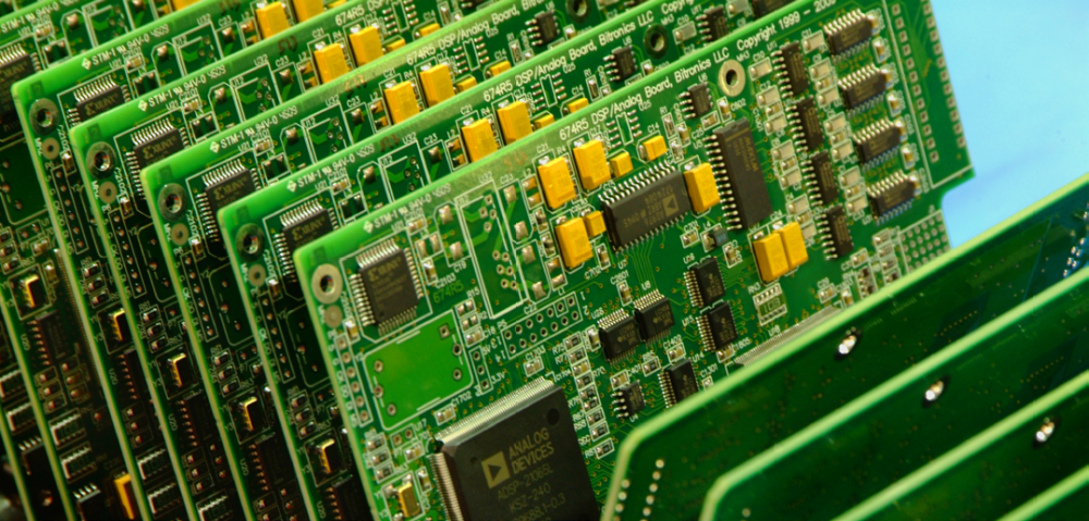
In a PCB board (printed circuit board) there are many errors that are common when designing them. The customer will always request a circuit model, but that may not be functional and practical. Click here for hdi pcb.
The PCB design professional should provide the best guidance to, among other things, facilitate his work. There is a world of possibilities in the design of these plates, and with them come errors. Here we will tell you how to avoid them so you don’t delay delivery. Visit this site for flexible circuit.
Mistakes you make most in a PCB design
If you learn what your mistakes are, you can increase success in your designs. Given this, we have created a list with the most common in PCB design. The idea is that you don’t repeat them or avoid them at all costs:
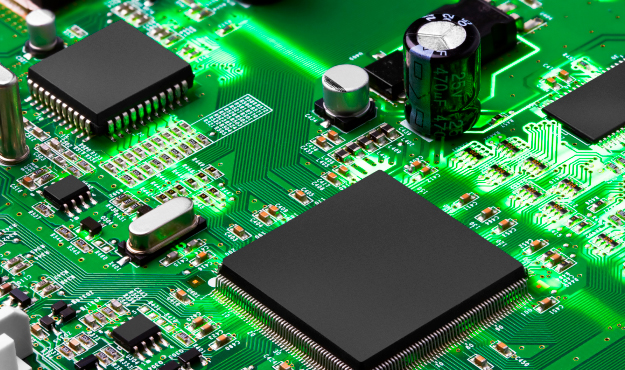
Distribution of the components on the PCB
When the components are poorly distributed on the PCB, the needs are not met from the electronic point of view. Given this, it is essential to consider:
All the components that protect the product such as the box, screws, nuts, studs, enclosure, among others. It is essential to have clear dimensions if it is not done, you have to run tracks to give the elements more space.
The wiring that connects the card with other external parts. The space can be small and not allow a comfortable and friendly distribution on the PCB. If the forecasts are not taken you will have to move routed tracks in the middle of the process.
Locating the components in appropriate spaces helps optimize space and provide greater comfort inside the box.
Plan the route
When routing is not planned, it can cause failures in the PCB or malfunction. To achieve a good route the location is key for that:
Locate them according to the electrical characteristics of the PCB
Locate the circuits according to the components depending on the nature of it
Very large tracks
Routing the printed circuit board as it is routed can become a headache. Routing channels are a solution and refers to the dimensions of the track. If we learn more about this concept, we will have a more real value of the track space.
The analog and the digital do not separate
Most separate analog and digital components by using grooves in grooves or separations. In this case, the ideal is to place them in a suitable space without having to make cuts in the ground. At this point, separations in analog and digital tracks are recommended. The goal is to avoid couplings in different directions.
No Routing the track at about 45º
In the past when designing the PCB, 90-degree tracks were drawn, but this changed because it was thought to generate a kind of radioactive emissions. However, studies and research evolved and demonstrated the critical situation.
For frequencies above 100 MHz, signals between 5 and 9% can be lost. In the case of frequencies above 500 MHz or 1GHz, curved strokes are recommended. This is why an angle of 45º improves the process and helps to take advantage of the routing channels with greater precision.